

Very easy programming
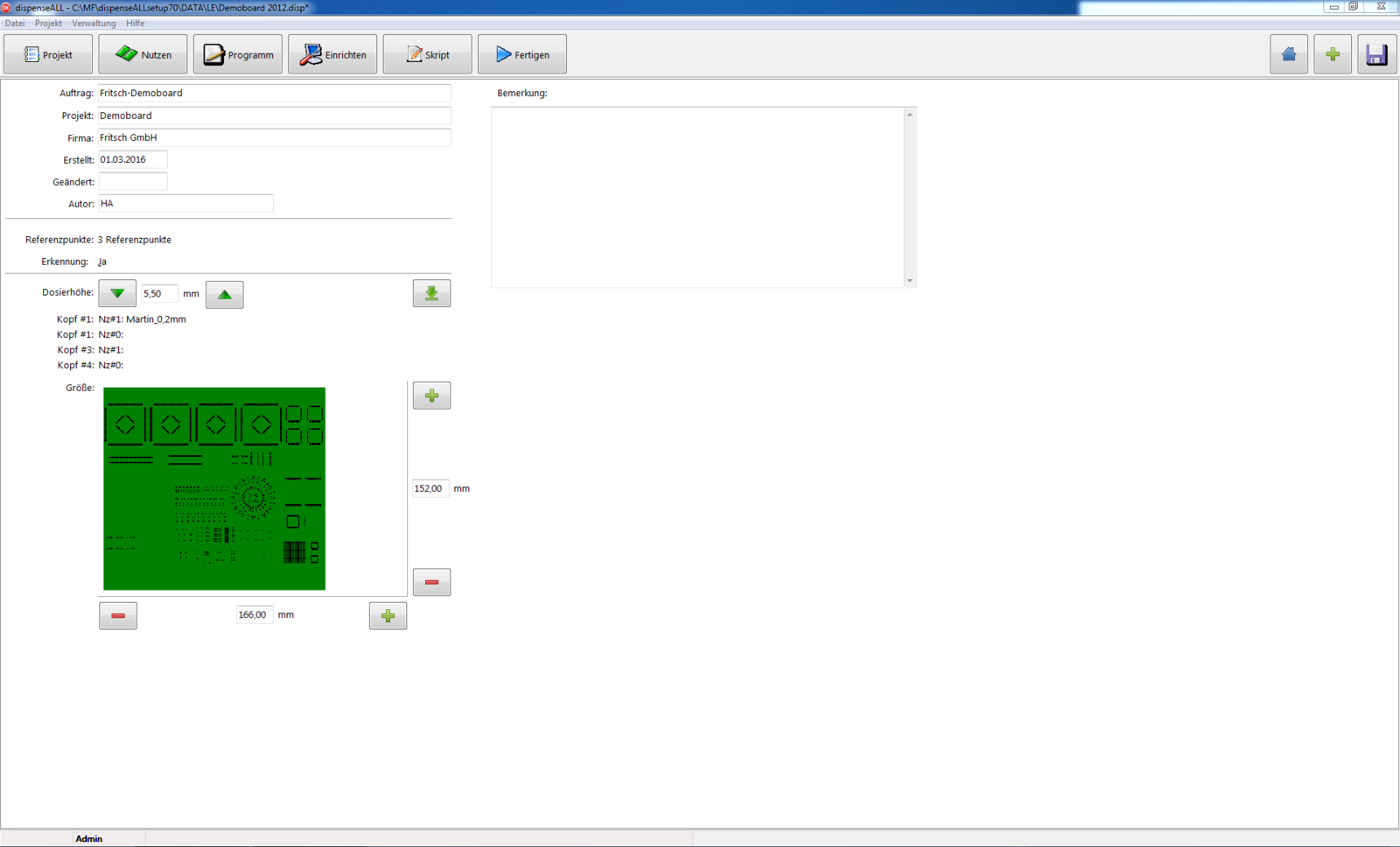
The dispensing programs are made directly from CAD or by the virtual editor. Plans or scans of the workpiece can be read in as background to write the dispensing scripts. Programming is as easy as using a drawing program.
Teach In
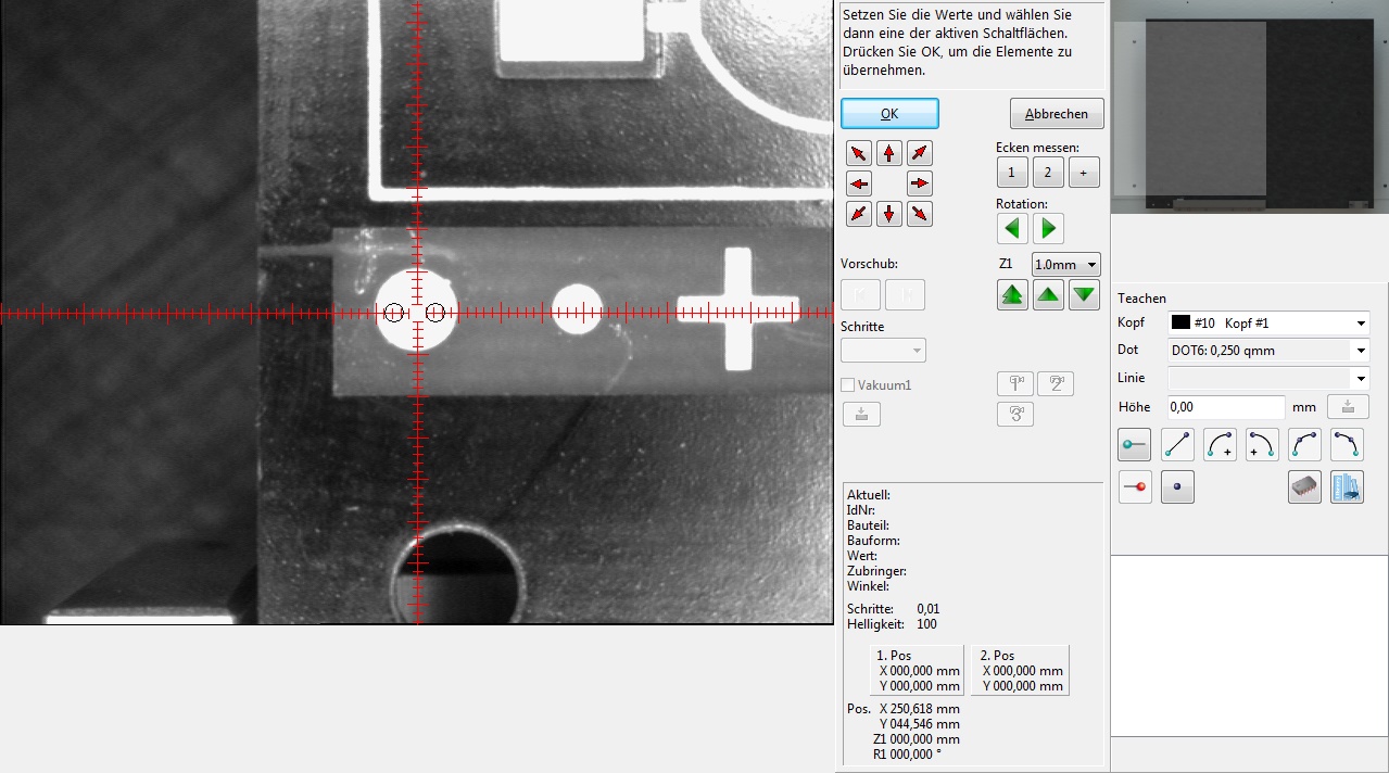
To create a dispensing program the user drives with the integrated head camera to the actual position. Standard elements like dots, lines, curves and circles are available. Time-consuming pattern like for example meandering shapes on surfaces are possible by prepared forms. The virtual display of the camera image enables the exact alignment of the dispensing on workpiece or PCB. Therefore times of programming and runs for testing are shortened.
Data transfer
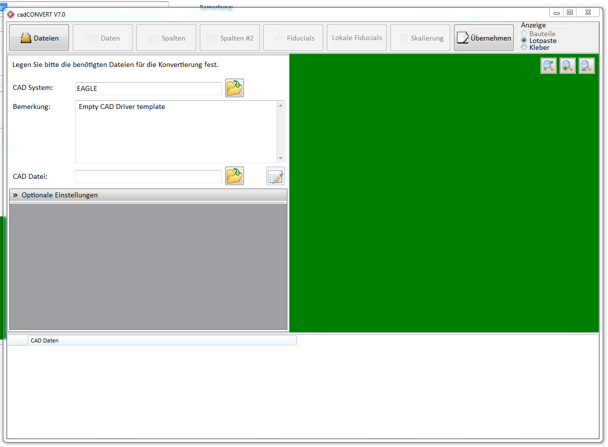
Existing CAD data can be used for the dispensing-positions. Gerber Data as well as CAD Data in ASCII code can be imported.
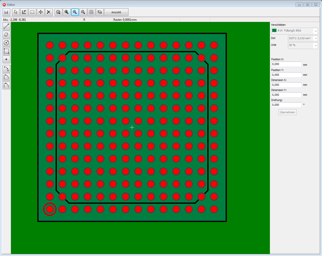
Gerber data conversion
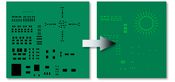
Common Gerber files are used to create dispensing points using template thickness and SMD pad information. Dot size, size and shape are easy to set and optimize for each component and pad on the board.

Dxf-Data conversion
By means of theX/Y-center coordinate and the drawing layer the allocation of the dispensing position and quantity takes place.
Virtual component editor
If there are further components necessary which aren't noted in the actual library a grafical component editor is available. Therefore new designs can be realized in just a few steps.

Component library
The integrated library contains over 450 componentmodels. This is one of the largest component library which is in this class available on market. All content items can be edited or new created.